Main Application:
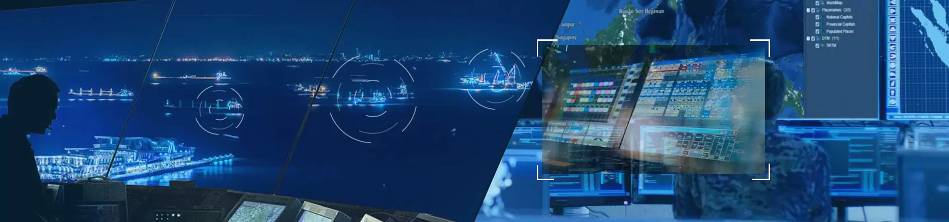
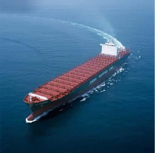
VTS system is composed of communication equipment, VTS radar, ship automatic identification system(AIS), closed circuit television(CCTV), hydro meteorological equipment, data processing system and so on. As the core sensing equipment of VTS, LW-R30-SH radar is a product developed in strict accordance with the requirements of the International Lighthouse Navigation Association (IALAV.128 Recommendation for VTS) for radar detection performance. The LW-R30-SH radar is capable of tracking and monitoring the position, speed, course and other parameters of the moving vessel on the surface of water. These parameters have time information of GPS or Beidou calibration. Meanwhile, the radar can also track and monitor the position of moored vessels, lighthouses and buoys, and provide basic data for VTS system.
LW-R30-SHradar can also be installed at coastal observatories or outposts to monitor all kinds of illegal activities near the coastline and to enhance the vigilance of law enforcement agencies. Illegal activities may be aimed at smuggling speedboats, illegal immigration vessels, pirate boats, illegal fishing vessels, polluting ships, and so on. This radar is the core monitoring equipment of sea-air early warning system for offshore wind farm, and is widely used in offshore wind farm.
Technical Characteristics:
Radar composition and configuration
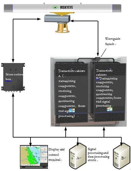
a) Configuration of dual-channel and single-channel radar systems
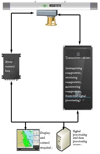
LW-R30-SH radar can configure dual-channel system or single-channel system according to user's needs. The configuration of dual-channel system is illustrated in Figure 1. The dual-channel transceiver system is equipped with a set of antennas, turntables, servo control and display terminals, while transmitters, receivers, signal processing and data processing equipment are equipped with two sets. When one of the transceiver channels fails, it can automatically switch to the other channel and continue to work. This configuration has higher task reliability, but the cost of the system is also high.In the single channel radar system, the antenna, turntable, servo control, transmitter, receiver, signal processing, data processing and display and control terminals are all equipped with only one set of devices, and the system configuration diagram is shown in Figure 2. The advantage of single-channel radar is that the construction cost is relatively low and the control is relatively simple. It is suitable for applications with low requirement for data support.
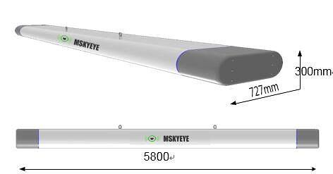
b) Radar Antenna
The standard configuration of LW-R30-SH radar is 5800mm antenna (see Fig.3). When the lower azimuth resolution or precision in practical application can also meet the requirement of application, lower cost antenna can be configured with shorter length antenna. Similarly, if the requirement for near-area coverage of radar detection is not high or the influence of rain clutter can be ignored, the components such as antenna lobe shaping and circular polarization can also be removed to reduce the cost of radar system.
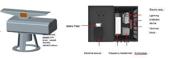
c) Antenna Turntable and Servo Control Box
The antenna turntable of the LW-R30-SH radar (see figure 4 to the left) is used to drive the antenna to a 360 °rotation scan, and the transmit power generated by the radar transmitter is transmitted to the antenna through the rotating joints in the turntable. The target echo RF signal is received by the antenna and transmitted to the radar receiver by rotating joint. The turntable is also equipped with azimuth encoder, oil temperature and oil level sensor and other equipment. On the right side of figure 4 is the servo control box that controls the rotation of the antenna turntable. The servo control case can be mounted in the indoor computer room by hanging the wall. The size of the chassis is: high x wide × deep=460 x 330 x 225mm³.
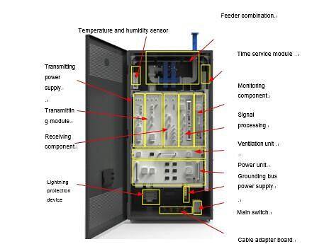
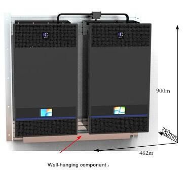
d) Transceiver cabinet
The LW-R30-SH radar transceiver cabinet (see Figure 5) contains indoor feeder assemblies (waveguides, loops, couplers, etc.), transmitting power, transmitting components, receiving components, signal processing, monitoring components, ventilation units, power supply units, lightning protection, satellite timing equipment, etc. The transceiver cabinet is wall-mounted. Figure 6 shows the wall diagram of the dual-channel radar transceiver cabinet.
e) Radar installation
LW-R30-SH radar equipment also includes signal processing data processing server, radar display and control terminal, waveguide aerator, etc.. Signal processing data processing server selects commercial server with higher main frequency and larger memory, and running clutter graph within server, MTI, constant false alarm rate, trace processing, track processing and other software. The radar display and control terminal is equipped with a commercial computer with high display resolution. It runs the target display and radar monitoring software on the computer. Data communication between server, computer, transceiver cabinet and servo control box is accomplished through LAN. In addition, according to the actual situation of the radar station, the antenna tower, lightning rod and installation, spare cabins, power distribution boxes, UPS, air conditioners should be selected. The radar installation diagram is shown in Figure 7
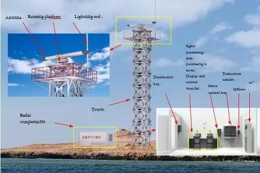
Figure 7 LW-R30-SH Installation Diagram